Figure 4.4-1: LANs are networks in IP jargon.
As we mentioned in Section 4.1, the Internet's network layer does not provide a virtual-circuit service, but instead a connectionless datagram service. When the network layer at the sending host receives a segment from the transport layer, it encapsulates the segment within an IP datagram, writes the destination address of the host (as well as other fields) on the datagram, and drops the datagram into the network. As we mentioned in Chapter 1, this process is similar to a person writing a letter, inserting the letter in an envelope, writing the destination address on the envelope, and dropping the envelope into a mailbox. Neither the Internet's network layer nor the postal service make any kind of preliminary contact with the destination before moving its "parcel" to the destination. Furthermore, as discussed in Section 4.1, the network layer service is a best effort service. It does not guarantee that the datagram will arrive within a certain time, it does not guarantee that a series of datagrams will arrive in the same order sent; in fact, it does not even guarantee that the datagram will ever arrive at its destination.
As we discussed in Section 4.1, the network layer for a datagram network, such as the Internet, has two major components. First, it has a network protocol component, which defines network-layer addressing, the fields in the datagram (i.e., the network layer PDU), and how the end systems and routers act on these fields. The network protocol in the Internet is called the Internet Protocol, or more commonly, the IP Protocol. There are currently two versions of the IP protocol in use today. In this section we examine the more widespread version, namely, Internet Protocol version 4, which is specified in [RFC 791] and which is more commonly known as IPv4. In Section 4.7 we shall examine, IPv6, which is expected to slowly replace IPv4 in the upcoming years.The second major component of the network layer is the path determination component, which determines the route a datagram follows from origin to destination. We study the path determination component in the next section.
Each IP address is 32 bits long (equivalently, four bytes) long. IP addresses are typically written in so-called "dot-decimal notation", whereby each byte of the address is written in its decimal form and is separated by a period. For example, a typical IP address would be 193.32.216.9. The 193 is the decimal equivalent for the first 8 bits of the address; the 32 is the decimal equivalent for the second 8 bits of the address, etc. Thus, the address 193.32.216.9 in binary notation is:
11000001 00100000 11011000 00001001
(A space as been added between the bytes for visual purposes.) Because each IP address is 32 bits long, there are 232 possible IP addresses.
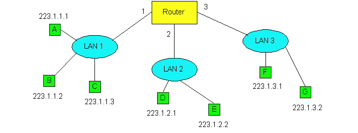
Figure 4.4-1: LANs are networks in IP jargon.
Figure 4.4-1 provides an example of IP addressing and interfaces. In
this figure there is one router which interconnects three LANs. (LANs,
also known as local area networks, were briefly discussed in Chatper 1
and will be studied in detail in the next chapter.) In the jargon of IP,
each of these LANs is called an IP network or more simply
a "network". There are several things to observe from this diagram.
First, the router has threes interfaces, labeled 1, 2 and 3. Each of the
router interfaces has its own IP address, which are provided in Figure
4.4-2; each host also has its own interface and IP address. Second, all
of the interfaces attached to LAN 1, including a router interface, have
an IP address of the form 223.1.1.xxx . Similarly, all the interfaces attached
to LAN 2 and LAN 3 have IP addresses of the form 223.1.2.xxx and 233.1.3.xxx,
respectively. In other words, each address has two parts: the first part
(the first three bytes in this example) that specifies the network; and
the second part (the last byte in this example) that addresses a specific
host on the network.
|
|
|
|
|
|
|
|
|
|
|
|
The IP definition of a "network" is not restricted to a LAN. To get some insight here, let us now take a look at another example. Figure 4.4-3 shows several LANs interconnected with three routers. All of the interfaces attached to LAN 1, including the router R1 interface that is attached to LAN 1, have an IP address of the form 223.1.1.xxx. Similarly, all the interfaces attached to LAN 2 and to LAN 3 have the form 223.1.2.xxx and 223.1.3.xxx, respectively. Each of the three LANs again constitute their own network (i.e., IP network). But note that there are three additional "networks" in this example: one network for the interfaces that connect Router 1 to Router 2; another network for the interfaces that connect Router 2 to Router 3; and a third network for the interfaces that connect Router 3 to Router 1.
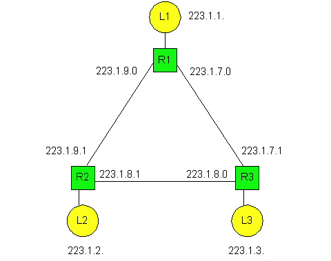
For a general interconnected system of routers and hosts (such as the Internet), we use the following recipe to define the "networks" in the system. We first detach each router interface from its router and each host interface from its host. This creates "islands" of isolated networks, with "interfaces" terminating all the leaves of the isolated networks . We then call each of these isolated networks a network. Indeed, if we apply this procedure to the internconnected system in Figure 4.4-3, we get six islands or "networks". The current Internet consists of millions of networks. (In the next chapter we will consider bridges. We mention here that when applying this recipe, we do not detach interfaces from bridges. Thus each bridge lies within the interior of some network.)
Now that we have defined a network, we are ready to discuss IP addressing in more detail. IP addresses are globally unique, that is, no two interfaces in the world have the same IP address. Figure 4.4-3 shows the four possible formats of an IP address. (A fifth address, beginning with 11110, is reserved for future use.) In general, each interface (for a host or router) belongs to a network; the network part of the address identifies the network to which the interface belongs. The host part identifies the specific interface within the network. (We would prefer to use the terminology "interface part of the address" rather than "host part of the address" because IP address is really for an interface and not for a host; but the terminology "host part" is commonly used in practice.) For a class A address, the first 8 bits identify the network, and the last 24 bits identify the interface within that network. Thus with a class A we can have up to 27 networks (the first of the eight bits is fixed as 0) and and 224 interfaces. Note that the interfaces in Figures 4-4.1 and 4-4.3 use class A addresses. The class B address space allows for 214 networks, with up to 216 interfaces within each network. A class C address uses 21 bits to identify the network and leaves only 8 bits for the interface identifier. Class D addresses are reserved for so-called multicast addresses. As we will see in Section 4.7, these addresses do not identify a specific interface but rather provide a mechanism through which multiple hosts can receive a copy of each single packet sent by a sender.
Figure 4.4-4: IPv4 address formats.
Before leaving our discussion of addressing, we want to mention that mobile hosts may change the network to which they are attached, either dynamically while in motion or on a longer time scale. Because routing is to a network first, and then to a host within the network, this means that the mobile host's IP address must change when the host changes networks. Techniques for handling such issues are now under development within the IETF and the research community [RFC2002] [RFC2131].

Figure 4.4-5: The key fields in an IP datagram.
Once the source host creates the IP datagram, how does the network layer transport the datagram from the source host to the destination host? Let us answer this question in the context of network Figure 4.4-1. First suppose host A wants to send an IP datagram to host B. The datagram is transported from host A to host B as follows. IP in host A first extracts the network portion of the address, 223.1.1. , and scans its routing table, which is shown in Figure 4.4-6. In this table, the "number of hops to destination" is defined to be the number of networks that need to be traversed, including the destination network. Scanning the table, host A finds a match in the first row, and observes that the number of hops to the destination is 1. This indicates to host A that the destination host is on the same network. Host A then passes the IP datagram to the link layer protocol and indicates to the link layer protocol that the destination is on the same LAN. The link layer protocol then has the responsibility of transporting the datagram to host B. (We will study how the link layer transports a datagram between to interfaces on the same network in the next chapter.)
|
network |
router |
of hops to destination |
|
|
|
|
|
|
|
|
|
|
|
|
Now consider the more interesting case of host A sending an IP datagram to host E, which has IP address 223.1.2.2 and is on a different LAN. Host A again scans its routing table, but now finds a match in the second row. Because the number of hops to the destination is 2, host A knows that the destination is on another network. The routing table also tells host A that in order to get the datagram to host E, host A should first send the datagram to router address 223.1.1.4. IP in host A then passes the datagram down to the link layer, and indicates to the link layer that it should first send the datagram to IP address 223.1.1.4 .The link layer then transports the datagram to the router interface 1. The datagram is now in the router, and it is the job the router to move the datagram towards the datagram's ultimate destination. The router extracts the network portion of the destination address of the IP datagram, namely 223.1.2. , and scans its routing table, which is shown in Figure 4.4-7. The router finds a match in the second row of the table. The table tells the router that the datagram should be forwarded on router interface 2; also the number of hops to the destination is 1, which indicates to the router that the destination host is on the LAN directly attached to interface 2. The router moves the datagram to interface 2. (The moving of a datagram from in input interface to an output interface within a router will be covered in Section 4.6.) Once the datagram is at interface 2, the router passes the datagram to link layer protocol and indicates to the link layer protocol that the destination host is on the same LAN. The link layer protocol has the job of transporting the datagram from the router interface 2 to host E, both of which are attached to the same LAN.
|
network |
router |
of hops to destination |
|
|
|
|
|
|
|
|
|
|
|
|
|
|
|
|
In Figure 4.4-7, note that the entries in the "next router" column are all empty. This is because all of the networks (223.1.1. , 223.1.2. , and 223.1.3. ) are each directly attached to the router, that is, there is no need to go through an intermediate router to get to the destination host. However, if host A and host E were separated by two routers, then within the routing table of the first router along the path from A to B, the appropriate row would indicate 2 hops to the destination and would specify the IP address of the second router along the path. The first router would then forward the datagram to the second router, using the link layer protocol that connects the two routers. The second router then forwards the datagram to the destination host, using the link layer protocol that connects the second router to the destination host.
You may recall from Chapter 1 that we said that routing a datagram in the Internet is similar to a person driving a car and asking gas station attendants at each intersection along the way how to get to the ultimate destination. It should now be clear why this an appropriate analogy for routing in the Internet. As a datagram travels from source to destination, it visits a series of routers. At each router in the series, it stops and asks the router how to get to its ultimate destination. Unless the router is on the same LAN as the ultimate destination, the routing table essentially says to the datagram: "I don't know exactly how to get to the ultimate destination, put I do know that the ultimate destination is in the direction of the link (analogous to a road) connected to interface 3." The datagram then sets out on the link connected to interface 3, arrives at a new router, and again asks for new directions.
From this discussion we see that the routing tables in the routers play a central role in routing datagrams through the Internet. But how are these routing tables configured and maintained for large networks with mulitple paths between sources and destinations (such as in the Internet)? Clearly, these routing tables should be configured so that the datagrams follow good (if not optimal) routes from source to destination. As you probably guessed, routing algorithms - like those studied in Section 4.2 - have the job of configuring and maintaining the routing tables. Furthermore, as discussed in Section 4.3, the Internet is partitioned into autonomous systems (ASs): intra-AS routing algorithms independently configure the routing tables within the autonomous systems; inter-AS routing algorithms have the job configuring routing tables so that datagrams can pass through multiple autonomous systems. We will discuss the Internet's intra-AS and inter-AS routing algorithms in Section 4.5. But before moving on to routing algorithms, we cover three more important topics for the IP protocol, namely, the datagram format, datagram fragmentation, and the Internet Control Message Protocol (ICMP).
The key fields in the IPv4 datagram are the following:
To understand the problem better, imagine that you are a router that interconnects several links, each running different link-layer protocols with different MTUs. Suppose you receive an IP datagram from one link, you check your routing table to determine the outgoing link, and this outgoing link has an MTU that is smaller than the length of the IP datagram. Time to panic -- how are you going to squeeze this oversized IP packet into the payload field of the link-layer packet? The solution to this problem is to "fragment" the data in the IP datagram among two or more smaller IP datagrams, and then send these smaller datagrams over the outgoing link. Each of these smaller datagrams is referred to as a fragment.
Fragments need to be reassembled before they reach the transport layer at the destination. Indeed, both TCP and UDP are expecting to receive from the network layer complete, un-fragmented segments. The designers of IPv4 felt that reassembling (and possibly re-fragmenting) datagrams in the routers would introduce significant complication into the protocol and put a damper on router performance. (If you were a router, would you want to be reassembling fragments on top of everything else you have to do?) Sticking to end-to-end principle for the Internet, the designers of IPv4 decided to put the job of datagram reassembly in the end systems rather than in the network interior.
When a destination host receives a series of datagrams from the same
source, it needs to determine if any of these datagrams are fragments of
some "original" bigger datagram. If it does determine that some datagrams
are fragments, it must further determine when it has received the last
fragment and how the fragments it has received should be pieced back together
to form the original datagram. To allow the destination host to perform
these reassembly tasks, the designers of of IP (version 4) put identification,
flag and fragmentation fields in the IP datagram. When
a datagram is created, the sending host stamps the datagram with an identification
number as well as a source and destination address. The sending host increments
the identification number for each datagram it sends. When a router needs
to fragment a datagram, each resulting datagram (i.e., "fragment") is stamped
with the source address, destination address and identification number
of the original datagram. When the destination receives a series of datagrams
from the same sending host, it can examine the identification numbers of
the datagrams to determine which of the datagrams are actually fragments
of the same bigger datagram. Because IP is an unreliable service,
one or more of the fragments may never arrive at the destination. For this
reason, in order for the destination host to be absolutely sure it has
received the last fragment of the original datagram, the last fragment
has a flag bit set to 0 whereas all the other fragments have this flag
bit set to 1. Also, in order for the destination host to determine if a
fragment is missing (and also to be able to reassemble the fragments in
the proper order), the offset field is used to specify where the fragment
fits within the original IP datagram. This bit is set to 1 in all except
the last fragment.
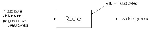
Figure 4.4-9: IP Fragmentation
Figure 4.4-9 illustrates an example. A datagram 4,000 bytes arrives to a router, and this datagram must be forwarded to a link with a MTU of 1500 bytes. These implies that the 3,980 data bytes in the original datagram must be allocated to three separate fragments (each of which are also IP datagrams). Suppose that the original datagram is stamped with an identification number of 777. Then the characteristics of the three fragments are as follows:
Fragmentation and reassembly puts an additional burden on Internet routers (the additional effort to create fragments out of a datagram) and on the destination hosts (the additional effort to reassembly fragments). For this reason it is desirable to keep fragmentation to a minimum. This is often done by limiting the TCP and UDP segments to a relatively small size, so that the fragmentation of the corresponding datagrams is unlikely. Because all data link protocols supported by IP are supposed to have MTUs of at least 576 bytes, fragmentation can be entirely eliminated by using a MSS of 536 bytes, 20 bytes of TCP segment header and 20 bytes of IP datagram header. This is why most TCP segments for bulk data transfer (such as with HTTP) are 512-536 bytes long. (You may have noticed while surfing the Web that 500 or so bytes of data often arrive at a time.)
Following this section we provide a Java applet that generates fragments. You provide the incoming datagram size, the MTU and the incoming datagram identification. It automatically generates the fragments for you.
ICMP is often considered part of IP, but architecturally lies just above IP, as ICMP messages are carried inside IP packets. That is, ICMP messages are carried as IP payload, just as TCP or UDP packets are carried at IP payload. Similarly, when an host receives an IP packet with ICMP specified as the upper layer protocol, it demultiplexes the packet to ICMP, just as it would demultiplex a packet to TCP or UDP.
ICMP messages have a type and a code field, and also contain the first
8 bytes of the IP packet that caused the IP message to be generated in
the first place (so that the sender can determine which packet is sent
that caused the error). Selected ICMP messages are shown below in
Figure 4.4-10. Note that ICMP messages are used not only for signaling
error conditions. The well-known ping [ping man
page] program uses ICMP. ping sends an ICMP type 8 code 0 message
to the specified host. The destination host, seeing the echo request
sends back an type 0 code 0 ICMP echo reply. Another interesting
ICMP message is the source quench message. This message is seldom
used in practice. Its original purpose was to perform congestion
control -- to allow a congested router to send an ICMP source quench message
to a host to force that host to reduce its transmission rate. We
have seen in Chapter 3 that TCP has its own congestion control mechanism
that operates at the transport layer, without the use of network layer
support such as the ICMP source quench message.
| ICMP type | code | description |
| 0 | 0 | echo reply (to ping) |
| 3 | 0 | destination network unreachable |
| 3 | 1 | destination host unreachable |
| 3 | 2 | destination protocol unreachable |
| 3 | 3 | destination port unreachable |
| 3 | 6 | destination network unknown |
| 3 | 7 | destination host unknown |
| 4 | 0 | source quench (congestion control) |
| 8 | 0 | echo request |
| 9 | 0 | router advertisement |
| 10 | 0 | router discovery |
| 11 | 0 | TTL expired |
| 12 | 0 | IP header bad |
In Chapter 1 we introduced the Traceroute program,
which enabled you to trace the route from a few given hosts to any host
in the world. Interesting enough, Traceroute also uses ICMP messages. To
determine the names and addresses of the routers between source and destination,
Traceroute in the source sends a series of ordinary IP datagrams to the
destination. The first of these datagrams has a TTL of 1, the second of
2, the third of 3, etc. The source also starts timers for each of
the datagrams. When the nth datagram arrives at the nth router, the nth
router observers that the TTL of the datagram has just expired. According
to
the rules of the IP protocol, the router discards the datagram (because
there may be a routing loop) and sends an ICMP warning message to the source
(type 11 code 0). This warning message includes the name of the router
and its IP address. When the ICMP message corresponding to the nth datagram
arrives at the source, the source obtains the round-trip time from the
timer and the name and IP address from the ICMP message. Now that you understand
how Traceroute works, you may want to go back and play with it some more.
If you are interested in an Internet Draft relating to a certain subject or protocol enter the keyword(s) here.