Figure 5.3-1: Various multiple access channels
Figure 5.3-1: Various multiple access channels
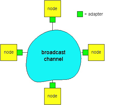
We are all familiar with the notion of broadcasting, as television has been using it since its invention. But traditional television is a one-way broadcast (i.e., one fixed node transmitting to many receiving nodes), while nodes on a computer network broadcast channel can both send and receive. Perhaps a more apt human analogy for a broadcast channel is a cocktail party, where many people gather together in a large room (the air providing the broadcast medium) to talk and listen. A second good analogy is something many readers will be familiar with - a classroom - where teacher(s) and student(s) similarly share the same, single, broadcast medium. A central problem in both scenarios is that of determining who gets to talk (i.e., transmit into the channel), and when. As humans, we've evolved an elaborate set of protocols for sharing the broadcast channel ("Give everyone a chance to speak." "Don't speak until you are spoken to." "Don't monopolize the conversation." "Raise your hand if you have question." "Don't interrupt when someone is speaking." "Don't fall asleep when someone else is talking.").
Computer networks similarly have protocols - so-called multiple access
protocols - by which nodes regulate their transmission onto the shared
broadcast channel. As shown in Figure 5.3-1, multiple access protocols
are needed in a wide variety of network settings, including both wired
and wireless local area networks, and satellite networks. Figure 5.3-2
takes a more abstract view of the broadcast channel and of the nodes sharing
that channel. Although technically each node accesses the broadcast channel
through its adapter, in this section we will refer to the node as
the sending and receiving device. In practice, hundreds or even thousands
of nodes can directly communicate over a broadcast channel.
Because all nodes are capable of transmitting frames, more than two nodes can transmit frames at the same time. When this happens, all of the nodes receive multiple frames at the same time, that is, the transmitted frames collide at all of the receivers. Typically, when there is a collision, none of the receiving nodes can make any sense of any of the frames that were transmitted; in a sense, the signals of the colliding frame become inextricably tangled together. Thus, all the frames involved in the collision are lost, and the broadcast channel is wasted during the collision interval. Clearly, if many nodes want to frequently transmit frames, many transmissions will result in collisions, and much of the bandwidth of the broadcast channel will be wasted.
In order to ensure that the broadcast channel performs useful work when multiple nodes are active, it is necessary to somehow coordinate the transmissions of the active nodes. This coordination job is the responsibility of the multiple access protocol. Over the past thirty years, thousands of papers and hundreds of Ph.D. dissertations have been written on multiple access protocols; a comprehensive survey of this body of work is [Rom 1980] Furthermore, dozens of different protocols have been implemented in a variety of link-layer technologies. Nevertheless, we can classify just about any multiple access protocol as belonging to one of three categories: channel partitioning protocols, random access protocols, and taking-turns protocols. We'll cover these categories of multiple access protocols in the following three subsections. Let us conclude this overview by noting that ideally, a multiple access protocol for a broadcast channel of rate R bits per second should have the following desirable characteristics:
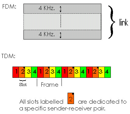
Figure 5.3-3: A four-node TDM and FDM example
TDM is appealing as it eliminates collisions and is perfectly fair: each node gets a dedicated transmission rate of R/N bps during each slot time. However, it has two major drawbacks. First, a node is limited to this rate of R/N bps over a slot's time even when it is the only node with frames to send. A second drawback is that a node must always wait for its turn in the transmission sequence - again, even when it is the only node with a frame to send. Imagine the partygoer who is the only one with anything to say (and imagine that this is the even rarer circumstance where everyone at the party wants to hear what that one person has to say). Clearly, TDM would be a poor choice for a multiple access protocol for this particular party.
While TDM shares the broadcast channel in time, FDM divides the R bps channel into different frequencies (each with a bandwidth of R/N) and assigns each frequency to one of the N nodes. FDM thus creates N "smaller" channels of R/N bps out of the single, "larger" R bps channel. FDM shares both the advantages and drawbacks of TDM. It avoids collisions and divides the bandwidth fairly among the N nodes. However, FDM also shares a principal disadvantage with TDM - a node is limited to a bandwidth of R/N, even when it is the only node with frames to send.
A third channel partitioning protocol is Code Division Multiple Access (CDMA). While TDM and FDM assign times slots and frequencies, respectively, to the nodes, CDMA assigns a different code to each node. Each node then uses its unique code to encode the data bits it sends, as discussed below. We'll see that CDMA allows different nodes to transmit simultaneously and yet have their respective receivers correctly receive a sender's encoded data bits (assuming the receiver knows the sender's code) in spite of "interfering" transmissions by other nodes. CDMA has been used in military systems for some time (due its anti jamming properties) and is now beginning to find widespread civilian use, particularly for use in wireless multiple access channels.
In a CDMA protocol, each bit being sent by the sender is encoded by multiplying the bit by a signal (the code) that changes at a much faster rate (known as the chipping rate) than the original sequence of data bits. Figure 5.3-4 shows a simple, idealized CDMA encoding/decoding scenario. Suppose that the rate at which original data bits reach the CDMA encoder defines the unit of time; that is, each original data bit to be transmitted requires one bit-slot time. Let di be the value of the data bit for the ith bit slot. Each bit slot is further subdivided into M mini-slots; in Figure 5.3-4, M=8, although in practice M is much larger. The CDMA code used by the sender consists of a sequence of M values, cm, m = 1,...,M, each taking a +1 or -1 value. In the example in Figure 5.3-4, the M-bit CDMA code being used by the sender is (1, 1, 1, -1, 1, -1, -1, -1).
Figure 5.3-4: A simple CDMA example: sender encoding, receiver
decoding
To illustrate how CDMA works, let us focus on the ith data bit, di. For the mth mini-slot of the bit-transmission time of di, the output of the CDMA encoder, Zi,m, is the value of di multiplied by the mth bit in the assigned CDMA code, cm:
In a simple world, with no interfering senders, the receiver would receive the encoded bits, Zi,m, and recover the original data bit, di, by computing:
di = (1/M) Sm=1,M Zi,m . cm (Equation 5.3-2)
The reader might want to work through the details of the example in Figure 5.3-4 to see that the original data bits are indeed correctly recovered at the receiver using Equation 5.3-2
The world is far from ideal, however, and as noted above, CDMA must work in the presence of interfering senders that are encoding and transmitting their data using a different assigned code. But how can a CDMA receiver recover a sender's original data bits when those data bits are being tangled with bits being transmitted by other senders? CDMA works under the assumption that the interfering transmitted bit signals are additive, e.g., that if three senders send a 1 value, and a fourth sender sends a -1 value during the same mini-slot, then the received signal at all receivers during hat mini-slot is a 2 (since 1+ 1 + 1 - 1 = 2). In the presence of multiple senders, sender s computes its encoded transmissions, Zi,m s , in exactly the same manner as in Equation 5.3-1. The value received at a receiver during the mth minislot of the ith bit slot, however, is now the sum of the transmitted bits from all N senders during that minislot:
Zi,m * = Ss=1,N Zi,m s
Amazingly, if the senders' codes are chosen carefully, each receiver can recover the data sent by a given sender out of the aggregate signal simply by using the sender's code in exactly the same manner as in Equation 5.3-2:
di = (1/M) Sm=1,M Zim * . cm (Equation 5.3-3)
Figure 5.3-5 illustrates a two-sender CDMA example. The M-bit
CDMA code being used by the upper sender is (1, 1, 1, -1, 1, -1, -1, -1),
while the CDMA code being used by the lower sender is (1, -1, 1, 1, 1,
-1, 1, 1). Figure 5.3-5 illustrates a receiver recovering the original
data bits from the upper sender. Note that the receiver is able to
extract the data from sender 1 in spite of the interfering transmission
from sender 2. Returning to our cocktail party analogy, a CDMA protocol
is similar to having partygoers speaking in multiple languages; in such
circumstances humans are actually quite good at locking into the conversation
in the language they understand, while filtering out the remaining conversations
Figure 5.3-5: A two-sender CDMA example
Our discussion here of CDMA is necessarily brief and a number of difficult
issues must be addressed in practice. First, in order for the CDMA receivers
to be able to extract out a particular sender's signal, the CDMA codes
must be carefully chosen. Secondly, our discussion has assumed that
the received signal strengths from various senders at a receiver are the
same; this can be difficult to achieve in practice. There is a considerable
body of literature addressing these and other issues related to CDMA; see
[Pickholtz 1982, Viterbi95]
for details.
5.2.2. Random Access Protocols
The second broad class of multiple access protocols are so-called random access protocols. In a random access protocol, a transmitting node always transmits at the full rate of the channel, namely, R bps. When there is a collision, each node involved in the collision repeatedly retransmit its frame until the frame gets through without a collision. But when a node experiences a collision, it doesn't necessarily retransmit the frame right away. Instead it waits a random delay before retransmitting the frame. Each node involved in a collision chooses independent random delays. Because after a collision the random delays are independently chosen, it is possible that one of the nodes will pick a delay that is sufficiently less than the delays of the other colliding nodes, and will therefore be able to "sneak" its frame into the channel without a collision.
There are dozens if not hundreds of random access protocols described in the literature [Rom 1990, Bertsekas 1992]. In this section we'll describe a few of the most commonly used random access protocols - the ALOHA protocols [Abramson 1970, Abramson 1985] and the Carrier Sense Multiple Access (CSMA) protocols [Kleinrock 1975]. Later, in section 5.5, we'll cover the details of Ethernet [Metcalfe 1976], a popular and widely deployed CSMA protocol.
Slotted ALOHA
Let's begin our study of random access protocols with one of the most simple random access protocols, the so-called slotted ALOHA protocol. In our description of slotted ALOHA, we assume the following:
Slotted ALOHA would appear to have many advantages. Unlike channel partitioning, slotted ALOHA allows a single active node (i.e., a node with a frame to send) to continuously transmit frames at the full rate of the channel. Slotted ALOHA is also highly decentralized, as each node detects collisions and independently decides when to retransmit. (Slotted ALOHA does, however, require the slots to be synchronized in the nodes; we'll shortly discuss an unslotted version of the ALOHA protocol, as well as CSMA protocols; noe of which require such synchronization and are therefore fully decentralized.) Slotted ALOHA is also an extremely simple protocol.
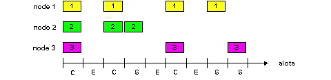
Slotted ALOHA also works great when there is only one active node, but how efficient is it when there are multiple active nodes? There are two possible efficiency concerns here. First, as shown in Figure 5.3-6, when there are multiple active nodes, a certain fraction of the slots will have collisions and will therefore be "wasted." The second concern is that another fraction of the slots will be empty because all active nodes refrain from transmitting as a result of the probabilistic transmission policy. The only "unwasted" slots will be those in which exactly one node transmits. A slot in which exactly one node transmits is said to be a successful slot. The efficiency of a slotted multiple access protocol is defined to be the long-run fraction of successful slots when there are a large number of active nodes, with each node having a large number of frames to send. Note that if no form of access control were used, and each node were to immediately retransmits after each collision, the efficiency would be zero. Slotted ALOHA clearly increases the efficiency beyond zero, but by how much?
We now proceed to outline the derivation of the maximum efficiency of slotted ALOHA. To keep this derivation simple, let's modify the protocol a little and assume that each node attempts to transmit a frame in each slot with probability p. (That is, we assume that each node always has a frame to send and that the node transmits with probability p for a fresh frame as well as for a frame that has already suffered a collision.) Suppose first there are N nodes. Then the the probability that a given slot is a successful slot is the probability that one of the nodes transmits and that the remaining N-1 nodes do not transmit. The probability that a given node transmits is p; the probability that the remaining nodes do not transmit is (1-p)N-1. Therefore the probability a given node has a success is p(1-p)N-1 . Because there are N nodes, the probability that an arbitrary node has a success is Np(1-p)N-1 .
Thus, when there are N active nodes, the efficiency of slotted ALOHA is Np(1-p)N-1 . To obtain the maximum efficiency for N active nodes, we have to find the p* that maximizes this expression. (See the homework problems for a general outline of this derivation.) And to obtain the maximum efficiency for a large number of active nodes, we take the limit of Np*(1-p*)N-1 as N approaches infinity. (Again, see homework problems.) After performing these calculations, we'll find that the maximum efficiency of the protocol is given by 1/e = .37. That is, when a large number of nodes have many frames to transmit, then (at best) only 37% of the slots do useful work. Thus the effective transmission rate of the channel is not R bps but only .37 R bps! A similar analysis also shows that 37% of the slots go empty and 26% of slots have collisions. Imagine the poor network administrator who has purchased a 100 Mbps slotted ALOHA system, expecting to be able to use the network to transmit data among a large number of users at an aggregate rate of, say, 80 Mbps! Although the channel is capable of transmitting a given frame at the full channel rate of 100Mbps, in the long term, the successful throughput of this channel will be less that 37 Mbps.
ALOHA
The slotted ALOHA protocol required that all nodes synchronize their transmissions to start at the beginning of a slot. The first ALOHA protocol [Abramson 1970] was actually an unslotted, fully decentralized, protocol. In so-called pure ALOHA, when a frame first arrives (i.e., a network layer datagram is passed down from the network layer at the sending node), the node immediately transmits the frame in its entirely into the broadcast channel. If a transmitted frame experiences a collision with one or more other transmissions, the node will then immediately (after completely transmitting its collided frame) retransmit the frame with probability p. Otherwise, the node waits for a frame transmission time. After this wait, it then transmits the frame with probability p, or waits (remaining idle) for another frame time with probability 1-p.
Figure 5.3-7: Interfering transmissions in pure Aloha
To determine the maximum efficiency of pure ALOHA, we focus on
an individual node. We'll make the same assumptions as in our slotted
ALOHA analysis and take the frame transmission time to be the unit of time
At any given time, the probability that a node is transmitting a frame
is p. Suppose this frame begins transmission at time t0.
As shown in Figure 5.3-7, in order for this frame to be successfully transmitted,
no other nodes can begin their transmission in the interval of time [t0-1,
t0]. Such a transmission would overlap with the beginning
of the transmission of node i's frame. The probability that
all other nodes do not begin a transmission in this interval is (1-p)N-1.
Similarly, no other node can begin a transmission while node i is
transmitting, as such a transmission would overlap with the latter part
of node i's transmission. The probability that all other nodes do
not begin a transmission in this interval is also (1-p)N-1.
Thus, the probability that a given node has a successful transmission is
p(1-p)2(N-1).
By taking limits as in the slotted ALOHA case, we find that the maximum
efficiency of the pure ALOHA protocol is only 1/(2e) - exactly half
that of slotted ALOHA. This then is the price to be paid for
a fully decentralized ALOHA protocol.
In both slotted and pure ALOHA, a node's decision to transmit is
made independently of the activity of the other nodes attached to the broadcast
channel. In particular, a node neither pays attention to whether
another node happens to be transmitting when it begins to transmit, nor
stops transmitting if another node begins to interfere with its transmission.
In our cocktail party analogy, ALOHA protocols are quite like a boorish
partygoer who continues to chatter away regardless of whether other people
are talking. As humans, we have human protocols that allow allows
us to not only behave with more civility, but also to decrease the amount
of time spent "colliding" with each other in conversation and consequently
increasing the amount of amount of data we exchange in our conversations.
Specifically, there are two important rules for polite human conversation:
The first question that one might ask about CSMA is that if all nodes perform carrier sensing, why do collisions occur in the first place? After all, a node will refrain from transmitting whenever it senses that another node is transmitting. The answer to the question can best be illustrated using space-time diagrams [Molle 1987]. Figure 5.3-7 shows a space-time diagram of four nodes (A, B, C, D) attached to an linear broadcast bus. The horizontal axis shows the position of each node in space; the y-axis represents time.
At time t0, node B senses the channel is idle, as no other nodes are currently transmitting. Node B thus begins transmitting, with its bits propagating in both directions along the broadcast medium. The downward propagation of B's bits in Figure 5.3-7 with increasing time indicates that a non-zero amount of time is needed for B's bits to actually propagate (albeit at near the speed-of-light) along the broadcast medium. At time t1 (t1 > t0), node D has a frame to send. Although node B is currently transmitting at time t1, the bits being transmitted by B have yet to reach D, and thus D senses the channel idle at t1. In accordance with the CSMA protocol, D thus begins transmitting its frame. A short time later, B's transmission begins to interfere with D's transmission at D. From Figure 5.3-7, it is evident that the end-to-end channel propagation delay of a broadcast channel - the time it takes for a signal to propagate from one of the the channel to another - will play a crucial role in determining its performance. The longer this propagation delay, the larger the chance that a carrier-sensing node is not yet able to sense a transmission that has already begun at another node in the network.
Figure 5.3-7: Space-time diagram of two CSMA nodes with colliding
transmissions
In Figure 5.3-7, nodes do not perform collision detection; both B and
D continue to transmit their frames in their entirety even though a collision
has occurred. When a node performs collision detection it will cease
transmission as soon as it detects a collision. Figure 5.3-8 shows
the same scenario as in Figure 5.3-7, except that the two nodes each abort
their transmission a short time after detecting a collision. Clearly,
adding collision detection to a multiple access protocol will help protocol
performance by not transmitting a useless, damaged (by interference with
a frame from another node) frame in its entirety. The Ethernet protocol
we will study in section 5.5 is a CSMA protocol that uses collision detection.
Figure 5.3-8: CSMA with collision detection.
5.2.2 Taking-Turns Protocols
Recall that two desirable properties of a multiple access protocol are (i) when only one node is active, the active node has a throughput of R bps, and (ii) when M nodes are active, then each active node has a throughput of nearly R/M bps. The ALOHA and CSMA protocols have this first property but not the second. This has motivated researchers to create another class of protocols -- the taking-turns protocols. As with random-access protocols, there are dozens of taking-turns protocols, and each one of these protocols has many variations. We'll discuss two of the more important protocols here. The first one is the polling protocol. The polling protocol requires one of the nodes to be designated as a "master node" (or requires the introduction of a new node serving as the master). The master node polls each of the nodes in a round-robin fashion. In particular, the master node first sends a message to node 1, saying that it can transmit up to some maximum number of frames. After node 1 transmits some frames (from zero up to the maximum number), the master node tells node 2 it can transmit up to the maximum number of frames. (The master node can determine when a node has finished sending its frames by observing the lack of a signal on the channel.) The procedure continues in this manner, with the master node polling each of the nodes in a cyclic manner.
The polling protocol eliminates the collisions and the empty slots that plague the random access protocols. This allows it to have a much higher efficiency. But it also has a few drawbacks. The first drawback is that the protocol introduces a polling delay, the amount of time required to notify a node that it can transmit. If, for example, only one node is active, then the node will transmit at a rate less than R bps, as the master node must poll each of the inactive nodes in turn, each time the active node sends its maximum number of frames. The second drawback, which is potentially more serious, is that if the master node fails, the entire channel becomes inoperative.
The second taking-turn protocol is the token-passing protocol.
In this protocol there is no master node. A small, special-purpose frame
known as a token is exchanged among the nodes in some fixed order.
For example, node 1 might always send the token to node 2, node 2 might
always send the token to node 3, node N might always send the token to
node 1. When a node receives a token, it holds onto the token only if it
has some frames to transmit; otherwise, it immediately forwards the token
to the next node. If a node does have frames to transmit when it receives
the token, it sends up to a maximum number of frames and then forwards
the token to the next node. Token passing is decentralized and has a high
efficiency. But it has its problems as well. For example, the failure of
one node can crash the entire channel. Or if a node accidentally neglects
to release the token, then some recovery procedure must be invoked to get
the token back in circulation? Over the years many token-passing products
have been developed, and each one had to address these as well as other
sticky issues.
5.2.3 Local Area Networks
Multiple access protocols are used in conjunction with many different types of broadcast channels. They have been used for satellite and wireless channels, whose nodes transmit over a common frequency spectrum. They are currently used in the upstream channel for cable access to the Internet (see Section 1.5). And they are extensively used in local area networks (LANs).
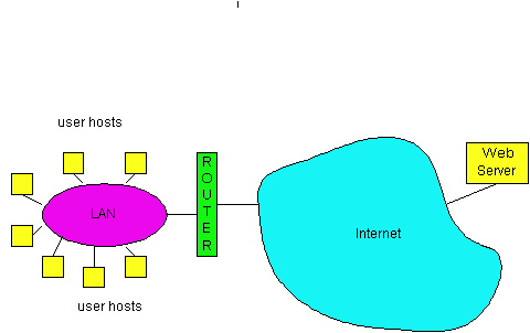
Recall that a LAN is a computer network that is concentrated in a geographical area, such as in a building or on a university campus. When a user accesses the Internet from a university or corporate campus, the access is almost always by way of a LAN. For this type of Internet access, the user's host is a node on the LAN, and the LAN provides access to the Internet through a router, as shown in Figure 5.3-9. The LAN is a single "link" between each user host and the router; it therefore uses a link-layer protocol, which incorporates a multiple access protocol. The transmission rate, R, of most LANs is very high. Even in the early 1980s, 10 Mbps LANs were common; today, 100 Mbps LANs are common, and 1 Gbps LANs are available.
In the 1980s and the early 1990s, two classes of LAN technologies were popular in the workplace. The first class consists of the Ethernet LANs (also known as 802.3 LANs [IEEE 1998b, Spurgeon 1999]), which are random-access based. The second class of LAN technologies are token-passing technologies, including token ring (also known as IEEE 802.5 [IEEE 1998]) and FDDI (also known as Fiber Distributed Data Interface [Jain 1994]). Because we shall explore the Ethernet technologies in some detail in Section 5.4, we focus our discussion here on the token-passing LANs. Our discussion on token-passing technologies is intentionally brief, since these technologies have become relatively minor players in the face of relentless Ethernet competition. Nevertheless, in order to provide examples about token-passing technology and to give a little historical perspective, it is useful to say a few words about token rings.
In a token ring LAN, the N nodes of the LAN (hosts and routers)
are connected in a ring by direct links. The topology of the token
ring defines the token-passing order. When a node obtains the token and
sends a frame, the frame propagates around the entire ring, thereby creating
a virtual broadcast channel. The node that sends the frame has the responsibility
of removing the frame from the ring. FDDI was designed for geographically
larger LANs (so called MANs, that is, metropolitan area networks). For
geographically large LANs (spread out over several kilometers) it is inefficient
to let a frame propagate back to the sending node once the frame has passed
the destination node. FDDI has the destination node remove the frame from
the ring. (Strictly speaking, FDDI is not a pure broadcast channel, as
every node does not receive every transmitted frame.) You can learn more
about token ring and FDDI by visiting the 3Com adapter page [3Com].
[Abramson 1970] N. Abramson,
"The Aloha system," AFIPS Conf. Proc., Vol. 37, 1970 Fall
Joint Computer Confernce, AFIPS Press, Montvale, N.J., 1970, pp. 281-285.
[Abramson 1985] N. Abramson, "Development
of the Alohanet," IEEE Transactions on Information Theory," Vol. IT-31,
No. 3 (March 1985), pp. 119-123.
[Bertsekas 1992] D. Bertsekas and
R. Gallager, Data Networks, Second Edition, Prentice Hall, Englewood Cliffs,
New Jersey, 1992.
[3Com 1999] http://www.3com.com/products/nics.html
[Boggs 1988] D. Boggs, J. Mogul,
and C. Kent, "Measured capacity of an Ethernet: myths and reality;" Proc
ACM Sigcomm 1988, pp. 222 - 234
[IEEE 1998] IEEE, Token Ring Access
Method (ISO/IEC 8802-5: 1998 and 8802-5 : 1998/Amd 1), 1998. See
the 802.5 standards page at http://www.8025.org/802.5/documents/
[IEEE 1998b] IEEE, "Carrier sense
multiple access with collision detection (CSMA/CD) access method and physical
layer specifications." See the IEEE 802.3 publication catalog at http://standards.ieee.org/catalog/IEEE802.3.html
[Jain 1994] R. Jain, "FDDI Handbook
: High-Speed Networking Using Fiber and Other Media," Addison-Wesley (Reading
MA, 1994).
[Kleinrock 1975] L. Kleinrock
and F. A. Tobagi, "Packet Switching in Radio Channels: Part I -- Carrier
Sense Multiple-Access Modes and Their Throughput-Delay Characteristics,"
IEEE
Transactions on Communications, Vol. COM-23, No. 12, pp. 1400-1416,
Dec. 1975.
[Lam 1980] S. Lam, A Carrier Sense
Multiple Access Protocol for Local Networks," Computer Networks,
Volume 4, pp. 21-32, 1980.
[Metcalfe 1976] R. Metcalfe, D.
Boggs, "Ethernet: Distributed packet switching for local computer networks,"
Communications
of the ACM, 19(7) (1976), pp. 395-404.
[Molle 87] M. Molle, "Space Time Analysis
of CSMA Protocol," IEEE Journal on Selected Areas in Communications,
1987.
[Pickholtz 1982] R. Pickholtz,
D. Schilling, L. Milstein, "Theory of Spread Spectrum Communication - a
Tutorial," IEEE Transactions on Communications, Col. COM-30,
No. 5 (May 1982), pp. 855-884.
[Rom 1990] R. Rom and M. Sidi, "Multiple
Access Protocols: Performance and Analysis," Springer-Verlag, New York,
1990.
[Spurgeon 1999] C. Spurgeon, "Charles
Spurgeon's Ethernet Web Site," http://wwwhost.ots.utexas.edu/ethernet/ethernet-home.html
[Viterbi 1995] A. Viterbi, CDMA:
Principles of Spread Spectrum Communication, Addison-Wesley, (Reading
MA 1995).
Copyright 1996-1999 James F. Kurose and Keith W. Ross, All Rights
Reserved