5.5 Ethernet
Ethernet has pretty much taken over the LAN market.
As recently as the 1980s and the early 1990s, Ethernet faced many challenges
from other LAN technologies, including token ring, FDDI and ATM. Some of
these other technologies succeeded at capturing a part of the market share
for a few years. But since its invention in the mid-1970, Ethernet has
continued to evolve and grow, and has held on to its dominant market share.
Today, Ethernet is by far the most prevalent LAN technology, and
is likely to remain so for the foreseeable future. One might say
that Ethernet has been to local area networking what
the Internet has been to global networking:
There are many reasons for Ethernet's success.
First, Ethernet was the first widely-deployed high-speed LAN. Because it
was deployed early, network administrators became intimately familiar with
Ethernet -- its wonders and its quirks -- and were reluctant to switch
over to other LAN technologies when they came on the scene. Second, token
ring, FDDI and ATM are more complex and expensive than Ethernet, which
further discouraged network administrators from switching over. Third,
the most compelling reason to switch to another LAN technology (such as
FDDI or ATM) was usually the higher data rate of the new technology; however,
Ethernet always fought back, producing versions that operated at equal
data rates or higher. Switched Ethernet was also introduced in the early
1990s, which further increased its effective data rates. Finally, because
Ethernet has been so popular, Ethernet hardware (in particular, network
interface cards) has become a commodity and is remarkably cheap. This low
cost is also due o the fact that Ethernet's multiple access protocol, CSMA/CD,
is totally decentralized, which has also contributed to the low cost and
simple design.
The original Ethernet LAN, as shown in Figure 5.5-1, was invented in
the mid 1970s by Bob Metcalfe. An excellent source of online information
about Ethernet is Spurgeon's Ethernet Web Site [Spurgeon
1999].
Figure 5.5-1: The original Metcalfe design led to the 10Base5
Ethernet standard, which included an interface cable that connected the
Ethernet adapter (i.e., interface) to an external transceiver. Drawing
taken from Charles Spurgeon's Ethernet Web Site.
5.5.1 Ethernet Basics
Today Ethernet comes in many shapes and forms. An
Ethernet LAN can have a "bus topology" or a "star topology." An Ethernet
LAN can run over coaxial cable, twisted-pair copper wire, or fiber optics.
Furthermore, Ethernet can transmit data at different rates, specifically,
at 10 Mbps, 100 Mbps and 1 Gbps. But even though Ethernet comes in many
flavors, all of the Ethernet technologies share a few important characteristics.
Before examining the different technologies, let's first take a look at
the common characteristics.
Ethernet Frame Structure
Given that there are many different Ethernet technologies
on the market today, what do they have in common, what
binds them together with a common name? First and foremost is the Ethernet
frame structure. All of the Ethernet technologies -- whether they use coaxial
cable or copper wire, whether they run at 10 Mbps, 100 Mbps or 1 Gbps --
use
the same frame structure.
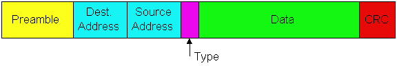
Figure 5.5-2: Ethernet frame structure
The Ethernet frame is shown in Figure 5.5-2. Once
we understand the Ethernet frame, we will already know a lot about Ethernet.
To put our discussion of the Ethernet frame in a tangible context, let
us consider sending an IP datagram from one host to another host, with
both hosts on the same Ethernet LAN. Let the sending adapter, adapter A,
have physical address AA-AA-AA-AA-AA-AA and the receiving adapter, adapter
B, have physical address BB-BB-BB-BB-BB-BB. The sending adapter encapsulates
the IP datagram within an Ethernet frame and passes the frame to the physical
layer. The receiving adapter receives the frame from the physical layer,
extracts the IP datagram, and passes the IP datagram to the network layer.
In this context, let us now examine the six fields
of the Ethernet frame:
-
Data Field (46 to 1500 bytes): This field
carries the IP datagram. The Maximum Transfer Unit (MTU) of Ethernet is
1500 bytes. This means that if the IP datagram exceeds 1500 bytes, then
the host has to fragment the datagram, as discussed in Section 4.4. The
minimum size of the data field is 46 bytes. This means that if the IP datagram
is less than 46 bytes, the data field has to be "stuffed" to fill
it out to 46 bytes. When stuffing is used, the data passed to the network
layer contains the stuffing as well as an IP datagram. The network layer
uses the length field in the IP datagram header to remove the stuffing.
-
Destination Address (6 bytes): This field
contains the LAN address of the destination adapter, namely, BB-BB-BB-BB-BB-BB.
When adapter B receives an Ethernet frame with destination address other
than its own physical address, BB-BB-BB-BB-BB-BB, or the LAN broadcast
address, it discards the frame. Otherwise, it passes the contents of the
data field to the network layer.
-
Source Address (6 bytes): This field contains
the LAN address of the adapter that transmits the frame onto the LAN, namely,
AA-AA-AA-AA-AA-AA.
-
Type Field (two bytes): The type field permits
Ethernet to "multiplex" network-layer protocols. To understand this idea,
we need to keep in mind that hosts can use other network-layer protocols
besides IP. In fact, a given host may support multiple network layer protocols,
and use different protocols for different applications. For this reason,
when the Ethernet frame arrives at adapter B, adapter B needs to know to
which network-layer protocol it should pass the contents of the data field.
IP and other data-link layer protocols (e.g., Novell IPX or AppleTalk)
each have there own, standardized type number. Furthermore, the ARP protocol
(discussed in the previous section) has its own type number. Note that
the type field is analogous to the protocol field in the network-layer
datagram and the port number fields in the transport-layer segment; all
of these fields serve to glue a protocol at one layer to a protocol at
the layer above.
-
Cyclic Redundancy Check (CRC) (4 bytes): As
discussed in section 5.2, the purpose of the CRC field is to allow the
receiving adapter, adapter B, to detect whether any errors have been introduced
into the frame, i.e., if bits in the frame have been toggled. Causes of
bit errors include attenuation in signal strength and ambient electromagnetic
energy that leaks into the Ethernet cables and interface cards. Error detection
is performed as follows. When host A constructs the Ethernet frame, it
calculates a CRC field, which is obtained from a mapping of the other
bits in frame (except for the preamble bits). When host B receives the
frame, it applies the same mapping to the frame and checks to see if the
result of the mapping is equal to what is in the CRC field. This operation
at the receiving host is called the CRC check. If the CRC check
fails (that is, if the result of the mapping does not equal the contents
of the CRC field), then host B knows that there is an error in the frame.
-
Preamble: (8 bytes) The Ethernet frame
begins with an eight-byte preamble field. Each of the first seven bytes
of
the preamble is 10101010; the last byte is 10101011. The first seven bytes
of the preamble serve to "wake up" the receiving adapters and to synchronize
their clocks to that of the sender's clock. Why should the clocks be out
of synchronization? Keep in mind that adapter A aims
to transmit the frame at 10 Mbps, 100 Mbps or 1 Gbps, depending on the
type of Ethernet LAN. However, because nothing is absolutely perfect, adapter
A will not transmit the frame at exactly the target rate; there will
always be some drift from the target rate, a drift which is
not known a priori by the other adapters on the LAN. A receiving
adapter can lock onto adapter A's clock by simply locking onto the bits
in the first seven bytes of the preamble. The last two bits of the eighth
byte of the preamble (the first two consecutive 1s) alert adapter B that
the "important stuff" is about to come. When host B sees the
two consecutive 1s, it know that the next six bytes is the destination
address. An adapter can tell when a frame ends by simply detecting absence
of current.
An Unreliable Connectionless Service
All of the Ethernet technologies provide connectionless
service to the network layer. That is to say, when adapter A wants
to send a datagram to adapter B, adapter A encapsulates the datagram in
an Ethernet frame and sends the frame into the LAN, without first "handshaking"
with adapter B. This layer-2 connectionless service is analogous to IP's
layer-3 datagram service and UDP's layer-4 connectionless service.
All the Ethernet technologies provide an unreliable
service to the network layer. In particular when adapter B receives
a frame from A, adapter B does not send an acknowledgment when a frame
passes the CRC check (nor does it send a negative acknowledgment when a
frame fails the CRC check). Adapter A hasn't the slightest idea whether
a frame arrived correctly or incorrectly. When a frame fails the CRC check,
adapter B simply discards the frame. This lack of reliable transport (at
the link layer) helps to make Ethernet simple and cheap. But it also means
that the stream of datagrams passed to the network layer can have gaps.
If there are gaps due to discarded Ethernet frames,
does the application-layer protocol at host B see gaps as well? As we learned
in Chapter 3, this solely depends on whether the application is using UDP
or TCP. If the application is using UDP, then the application-layer protocol
in host B will indeed suffer from gaps in the data. On the other hand,
if the application is using TCP, then TCP in host B will not acknowledge
the discarded data, causing TCP in host A to retransmit. Note that
when TCP retransmits data, Ethernet retransmits the data as well. But we
should keep in mind that Ethernet doesn't know that it is retransmitting.
Ethernet thinks it is receiving a brand new datagram with brand new data,
even though this datagram contains data that has already been transmitted
at least once.
Baseband Transmission and Manchester Encoding
Ethernet uses baseband transmission, that is, the adapter sends a digital
signal directly into the broadcast channel. The interface card does not
shift the signal into another frequency band, as do ADSL and cable modem
systems. Ethernet also uses Manchester encoding, as shown in Figure 5.5-3.
With Manchester encoding each bit contains a transition; a 1 has a transition
from up to down, whereas a zero has a transition from down to up. The reason
for Manchester encoding is that the clocks in the sending and receiving
adapters are not perfectly synchronized. By including a transition in the
middle of each bit, the receiving host can synchronize its clock to that
of the sending host. Once the receiving adapter's clock is synchronized,
the receiver can delineate each bit and determine whether it is a one or
zero. Manchester encoding is a physical layer operation rather than a link-layer
operation; however, we have briefly described it here as it is used extensively
in Ethernet.
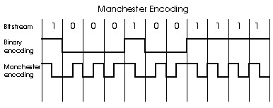
Figure 5.5-3: Manchester encoding
5.5.2 CSMA/CD: Ethernet's Multiple Access Protocol
Nodes in an Ethernet LAN are interconnected by a broadcast channel, so
that when an adapter transmits a frame, all the adapters on the LAN receive
the frame. As we discussed in section 5.3, Ethernet uses a CSMA/CD multiple
access algorithm. Summarizing our discussion from Section 5.3, recall that
CSMA/CD employs the following mechanisms:
-
An adapter may begin to transmit at any time, i.e., no slots are used.
-
An adapter never transmits a frame when it senses that some other adapter
is transmitting, i.e., it uses carrier-sensing.
-
A transmitting adapter aborts its transmission as soon as it detects that
another adapter is also transmitting, i.e., it uses collision detection.
-
Before attempting a retransmission, an adapter waits a random time that
is typically small compared to a frame time.
These mechanisms give CSMA/CD much better performance than slotted ALOHA
in a LAN environment. In fact, if the maximum propagation delay between
stations is very small, the efficiency of CSMA/CD can approach 100%. But
note that the second and third mechanisms listed above require each Ethernet
adapter to be able to (1) sense when some other adapter is transmitting,
and (2) detect a collision while it is transmitting. Ethernet adapters
perform these two tasks by measuring voltage levels before and during transmission.
Each adapter runs the CSMA/CD protocol without explicit coordination
with the other adapters on the Ethernet. Within a specific adapter, the
CSMA/CD protocol works as follows:
-
The adapter obtains a network-layer PDU from its parent node, prepares
an Ethernet frame, and puts the frame in an adapter buffer.
-
If the adapter senses that the channel is idle (i.e., there is no signal
energy from the channel entering the adapter), it starts to transmit the
frame. If the adapter senses that the channel is busy, it waits until it
senses no signal energy (plus a few hundred microseconds) and then starts
to transmit the frame.
-
While transmitting, the adapter monitors for the presence of signal energy
coming from other adapters. If the adapter transmits the entire frame without
detecting signal energy from other adapters, the adapter is done with the
frame.
-
If the adapter detects signal energy from other adapters while transmitting,
it stops transmitting its frame and instead transmits a 48-bit jam signal.
-
After aborting (i.e., transmitting the jam signal), the adapter enters
an exponential backoff phase. Specifically, when transmitting
a given frame, after experiencing the nth collision in a row
for this frame, the adapter chooses a value for K at random from
{0,1,2,...,2m - 1} where m:= min(n,10).
The adapter then waits K x 512 bit times and then returns to Step
2.
A few comments about the CSMA/CD protocol are certainly in order. The purpose
of the jam signal is to make sure that all other transmitting adapters
become aware of the collision. Let's look at an example. Suppose adapter
A begins to transmit a frame, and just before A's signal reaches adapter
B, adapter B begins to transmit. So B will have transmitted only a few
bits when it aborts its transmission. These few bits will indeed propagate
to A, but they may not constitute enough energy for A to detect the collision.
To make sure that A detects the collision (so that it to can also abort),
B transmits the 48-bit jam signal.
Next consider the exponential backoff algorithm. The first thing to
notice here is that a bit time (i.e., the time to transmit a single
bit) is very short; for a 10 Mbps Ethernet, a bit time is .1 microseconds.
Now let's look at an example. Suppose that an adapter attempts for the
first time to transmit a frame, and while transmitting it detects a collision.
The adapter then chooses K=0 with probability .5 and chooses K=1
with probability .5. If the adapter chooses K=0, then it immediately
jumps to Step 2 after transmitting the jam signal. If the adapter chooses
K=1,
it waits 51.2 microseconds before returning to Step 2. After a second collision,
K
is chosen with equal probability from {0,1,2,3}. After three collisions,
K
is chosen with equal probability from {0,1,2,3,4,5,6,7}. After ten
or more collisions, K is chosen with equal probability from {0,1,2,...,1023}.
Thus the size of the sets from which K is chosen grows exponentially
with the number of collisions (until n=10); it is for this reason
that Ethernet's backoff algorithm is referred to as "exponential backoff".
The Ethernet standard imposes limits on the distance between any two
nodes. These limits ensure that if adapter A chooses a lower value of K
than all the other adapters involved in a collision, then adapter A will
be able to transmit its frame without experiencing a new collision. We
will explore this property in more detail in the homework problems.
Why use exponential backoff? Why not, for example, select K from
{0,1,2,3,4,5,6,7} after every collision? The reason is that when an adapter
experiences its first collision, it has no idea how many adapters are involved
in the collision. If there are only a small number of colliding adapters,
it makes sense to choose K from a small set of small values.
On the other hand, if many adapters are involved in the collision, it makes
sense to choose K from a larger, more dispersed set of values (why?).
By increasing the size of the set after each collision, the adapter appropriately
adapts to these different scenarios.
We also note here that each time an adapter prepares a new frame for
transmission, it runs the CSMA/CD algorithm presented above. In particular,
the adapter does not take into account any collisions that may have occurred
in the recent past. So it is possible that an adapter with a new frame
will be able to immediately sneak in a successful transmission while
several other adapters are in the exponential backoff state.
Ethernet Efficiency
When only one node has a frame to send (which is typically the case), the
node can transmit at the full rate of the Ethernet technology (either 10
Mbps, 100 Mbps, or 1 Gbps). However, if many nodes have frames to transmit,
the effective transmission rate of the channel can be much less. We define
the efficiency of Ethernet to be the long-run fraction of time during
which frames are being transmitted on the channel without collisions when
there is a large number of active nodes, with each node having a large
number of frames to send. In order to present a closed-form approximation
of the efficiency of Ethernet, let tprop denote the maximum
time it takes signal energy to propagate between any two adapters. Let
ttrans be the time to transmit a maximum size Ethernet frame
(approximately 1.2 msecs for a 10 Mbps Ethernet). A derivation of the efficiency
of Ethernet is beyond the scope of this book (see [Lam
1980] and [Bertsekas 1992]). Here we simply
state the following approximation:
efficiency = 1/(1+ 5 tprop/ttrans).
We see from this formula that as tprop approaches 0,
the efficiency approaches 1. This is intuitive because if the propagation
delay is zero, colliding nodes will abort immediately without wasting the
channel. Also, as ttrans becomes very large, efficiency approaches
1. This is also intuitive because when a frame grabs the channel, it will
hold on to the channel for a very long time; thus the channel will
be doing productive work most of the time.
5.5.3 Ethernet Technologies
The most common Ethernet technologies today are 10Base2,
which uses thin coaxial cable in a bus topology and has a transmission
rate of 10 Mbps; 10BaseT, which uses twisted-pair cooper wire in a star
topology and has a transmission rate of 10 Mbps; 100BaseT, which typically
uses twisted-pair cooper wire in a star topology and has a transmission
rate of 100 Mbps; and Gigabit Ethernet, which uses both fiber and twisted-pair
cooper wire and transmits at a rate of 1 Gbps. These Ethernet technologies
are standardized by the IEEE 802.3 working groups. For this reason, Ethernet
is often referred to as an 802.3 LAN.
Before discussing specific Ethernet technologies, we need to discuss
repeaters,
which are commonly used in LANs as well as in wide-area transport. A repeater
is a physical-layer device that acts on individual bits rather than on
packets. It has two or more interfaces. When a bit, representing a zero
or a one, arrives from one interface, the repeater simply recreates the
bit, boosts its energy strength, and transmits the bit onto all the other
interfaces. Repeaters are commonly used in LANs in order to extend their
geographical range. When used with Ethernet, it is important to keep in
mind that repeaters do not implement carrier sensing or any other part
of CSMA/CD; a repeater repeats an incoming bit on all outgoing interfaces
even if there is signal energy on some of the interfaces.
10Base2 Ethernet
10Base2 is a very popular Ethernet technology. If you look at how your
computer (at work or at school) is connected to the network, it is very
possible you will see a 10Base2 connection. The "10" in 10Base2 stands
for "10 Mbps"; the "2" stands for "200 meters", which is the approximate
maximum distance between any two nodes without repeaters between them.
(The actual maximum distance is 185 meters.) A 10Base2 Ethernet is shown
in Figure 5.5-4.
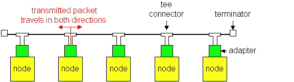
Figure 5.5-4: A 10Base2 Ethernet
We see from Figure 5.4.3 that 10Base2 uses a bus topology; that is,
nodes are connected (through their adapters) in a linear fashion. The physical
medium used to connect the nodes is thin coaxial cable, which is
similar to what is used in cable TV, but with a thinner and lighter cable.
When an adapter transmits a frame, the frame passes through a "tee connector;"
two copies of the frame leave the tee connector, one copy going in one
direction and one copy in the other direction. As the frames travel towards
the terminators, they leave a copy at every node they pass. (More precisely,
as a bit passes in front of a node, part of the energy of the bit leaks
into the adapter.) When the frame finally reaches a terminator, it gets
absorbed by the terminator. Note when an adapter transmits a frame, the
frame is received by every other adapter on the Ethernet. Thus, 10Base2
is indeed a broadcast technology.
Suppose you want to connect a dozen PCs in your office using 10Base2
Ethernet. To do this, you would need to purchase 12 Ethernet cards with
thin Ethernet ports; 12 BNC trees, which are small metalic objects that
attach to the adapters (less than one dollar each); a dozen or so thin
coax segments, 5-20 meters each; and two "terminators," which you put at
the two ends of the bus. The cost of the whole network, including adapters,
is likely to be less than the cost of a single PC! Because 10Base2 is incredibly
inexpensive, it is often referred to as "cheapnet".
Without a repeater, the maximum length of a 10Base2 bus is 185 meters.
If the bus becomes any longer, then signal attenuation can cause the system
to malfunction. Also, without a repeater, the maximum number of nodes is
30, as each node contributes to signal attenuation. Repeaters can be used
to connect 10Base2 segments in a linear fashion, with each segment having
up to 30 nodes and having a length up to 185 meters. Up to four repeaters
can be included in a 10Base2 Ethernet, which creates up to five "segments".
Thus a 10Base2 Ethernet bus can have a total length of 985 meters and support
up to 150 nodes. Note that the CSMA/CD access protocol is completely oblivious
to the repeaters; if any two of 150 nodes transmit at the same time, there
will be a collision. The online reader can learn more 10Base2 by visiting
Spurgeon's 10Base2
page.
10BaseT and 100BaseT
We discuss 10BaseT and100BaseT Ethernet together, as they are
similar technologies. The most important difference between them is that
10BaseT transmits at 10 Mbps and 100BaseT Ethernet transmits at 100 Mbps.
100BaseT is also commonly called "fast Ethernet" and "100 Mbps Ethernet".
10BaseT and 100BaseT are also very popular Ethernet technologies; in fact,
for new installations, 10BaseT and Ethernet are often today the technology
of choice. Both 10BaseT and 100BaseT Ethernet use a star topology,
as shown in Figure 5.5-5.
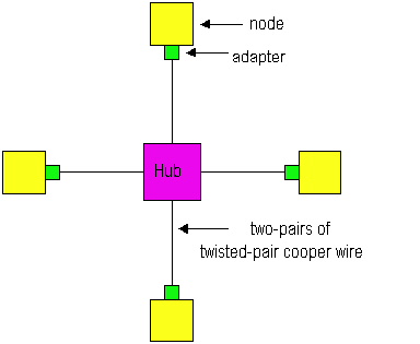
Figure 5.5-5: Star topology for 10BaseT and 100BaseT
In the star topology there is a central device called a hub (also
sometimes called a concentrator.) Each adapter on each node has a direct,
point-to-point connection to the hub. This connection consists of two pairs
of twisted-pair cooper wire, one for transmitting and the other for receiving.
At each end of the connection there is a connector that resembles the RJ-45
connector used for ordinary telephones. The "T" in 10BaseT and 100BaseT
stands for "twisted pair". For both 10BaseT and 100BaseT, the maximum
length of the connection between an adapter and the hub is 100 meters;
the maximum length between any two nodes is 200 meters. As we will discuss
in the next section, this maximum distance can be increased by using tiers
of hubs, bridges, switches and fiber links. A 10BaseT
In essence, a hub is a repeater: when it receives a bit from an adapter,
it sends the bit to all the other adapters. In this manner, each adapter
can (1) sense the channel to determine if it is idle, and (2) detect a
collision while it is transmitting. But hubs are popular because they also
provide network management features. For example, if an adapter malfunctions
and continually sends Ethernet frames (a so-called "jabbering adapter"),
then in a 10Base2 Ethernet will become totally dysfunctional; none of the
nodes will be able to communicate. But a 10BaseT network will continue
to function, because the hub will detect the problem and internally disconnect
the malfunctioning adapter. With this feature, the network administrator
doesn't have to get out of bed and drive back to work in order to correct
the problem for hackers who work late at night. Also, most hubs can gather
information and report the information to a host that connects directly
to the hub. This monitoring host provides a graphical interface that displays
statistics and graphs, such as bandwidth usage, collision rates, average
frame sizes, etc. Network administrators can use this information to not
only debug and correct problems, but also to plan how the LAN should
evolve in the future.
Many Ethernet adapters today are 10/100 Mbps adapters. This means that
they can be used for both 10BaseT and 100BaseT Ethernets. 100BaseT, which
typically uses category-5 twisted pair (a high-quality twisted pair with
a lot of twists). Unlike the 10Base2 and 10BaseT, 100BaseT does not use
Manchester encoding, but instead a more efficient encoding called 4B5B:
every group of five clock periods is used to send 4 bits in order to provide
enough transitions to allow clock synchronization.
The online reader can learn more about 10BaseT and 100BaseT by visiting
Spurgeon's
10BaseT page and Spurgeon's
100BaseTX page. The reader is also encouraged to read the following
articles from Data Communications on
100Mbps Ethernet:
We briefly mention at this point that both 10 Mbps and 100 Mbps Ethernet
technologies can employ fiber links. A fiber link is often used to interconnect
to hubs that are in different buildings on the same campus. Fiber is expensive
because of cost of the cost of its connectors, but it has excellent noise
immunity. The IEEE 802 standards permit a LAN to have a larger geographically
reach when fiber is used to connect backbone nodes.
Gigabit Ethernet
Gigabit Ethernet is an extension to the highly successful 10 Mbps and
100 Mbps Ethernet standards. Offering a raw data rate of 1000 Mbps, Gigabit
Ethernet maintains full compatibility with the huge installed base of Ethernet
equipment. The standard for Gigabit Ethernet, referred to as IEEE
802.3z, does the following:
-
Uses the standard Ethernet frame format (Figure 5.4.1), and is backward
compatible with 10BaseT and 100BaseT technologies. This allows for easy
integration of Gigabit Ethernet with the existing installed base of Ethernet
equipment.
-
Allows for point-to-point links as well as shared broadcast channels. Point-to-point
links use switches (see Section 5.6) where as broadcast channels use hubs,
as described above for 10BaseT and 100 BaseT. Un Gigabit Ethernet jargon,
hubs are called "buffered distributors".
-
Uses CSMA/CD for shared broadcast channels. In order to have acceptable
efficiency, the maximum distance between nodes must be severely restricted.
-
Allows for full-duplex operation at 1000 Mbps in both directions for point-to-point
channels.
Like 10BaseT and 100BaseT, Gigabit Ethernet has a star topology with a
hub or switch at its center. (Ethernet switches will be discussed in Section
5.6.) Gigabit Ethernet often serves as a backbone for interconnecting multiple
10 Mbps and 100 Mbps Ethernet LANs. Initially operating over optical fiber,
Gigabit Ethernet will be able to use Category 5 UTP cabling.
The Gigabit Ethernet Alliance is an open forum whose purpose is
to promote industry cooperation in the development of Gigabit Ethernet.
Their Web site is rich source of information on Gigabit Ethernet [Alliance
1999]. The Interoperability Lab at the University of New Hampshire
also maintains a nice page on Gigabit Ethernet [Inter
1999].
References
[Lam 1980] S. Lam, A Carrier Sense Multiple
Access Protocol for Local Networks," Computer Networks, Volume
4, pp. 21-32, 1980.
[Bertsekas 1992] D. Bertsekas and
R. Gallager, Data Networks, Second Edition, Prentice Hall, Englewood Cliffs,
New Jersey, 1992.
[Spurgeon 1999] C. Spurgeon, Charles
Spurgeon's Ethernet Web Site, http://wwwhost.ots.utexas.edu/ethernet/
[Alliance 1999] Gigabit Ethernet Alliance,
http://www.gigabit-ethernet.org/
[Inter 1999] Interoperability Lab Gigabit
Ethernet Page, http://www.iol.unh.edu/training/ge.html
Copyright 1996-1999 James F. Kurose
and Keith W. Ross. All Rights reserved.