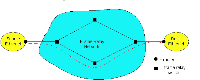
Figure 5.10-1: Public frame relay network interconnected two Ethernets through routers located on the Ethernets. The dotted line represents a virtual circuit.
Given that X.25 and frame relay are end-to-end WAN technologies, you may be wondering why we are discussing them in a chapter that is devoted to the data-link layer? We have chosen to discuss these technologies in this chapter for the same reason we chose to discuss ATM in this chapter -- all of these technologies are often employed today to carry IP datagrams from one IP router to another. Thus, from the perspective of IP (which is also an end-to-end WAN technology), X.25, frame relay and ATM are link layer technologies. Because IP is one of the protocols being highlighted in this book, we have put X.25, frame relay and ATM were IP believes these technologies belong, namely, in the link layer.
Although X.25 still exists throughout Europe and in certain nitch markets in North America, the X.25 networks are on the verge of extinction throughout the world. They were designed almost twenty years ago for a technological context that is very different from today's. Frame relay had great appeal to corporate customers throughout the 1990s, but it is increasingly fighting fierce competition from the public Internet. In fact, due to this competition, frame relay may become a minor player in the mid 2000s. Even though X.25 is on its way out (if not already completely gone), and frame relay may disappear as well a few years down the road, we have chosen to cover these technologies in this book because of their immense historical importance.
One way the designers put intelligence in the X.25 network was by employing virtual circuits in X.25 networks. Recall from Chapter 1 that virtual-circuit networks require the packet switches to maintain state information. In particular, the switch must maintain a table that maps inbound interface/VC-number to outbound interface/VC-number. Moreover, complex signalling protocols are needed to establish VCs and tear them down. As we learned in Chapter 4, the IP protocol is connectionless and, thus, does not use VCs. When a node wants to send an IP packet into the network it just stamps the datagram with a destination address and injects it into the network; it does not first request the network to establish a virtual circuit between itself and the destination.
Another important part of the technological context of the late 1970s and early 1980s conerns the physical links. In those days, almost all of the wired links were noisy, error-prone copper links. Fiber-optic links were only being researched in the laboratory at that time. Bit error rates over long-haul copper links were many orders of magnitude higher than they are now over fiber links. Because of the high error rates, it made sense to design X.25 protocol with error recovery on a hop-by-hop basis. In particular, whenever an X.25 switch sends a packet, it keeps a copy of the packet until the next switch (in the packet's route) returns an acknwoledgement. Thus each switch, when receiving a packet, performs error checking, and if the packet is error-free it sends an acknowledgement to the previous switch. Hop-by-hop error recovery significantly reduces link transmission rates, but it is consistent with the technological context of the era -- high link error rates and dumb terminals. The X.25 design also calls for flow-control on a hop-by-hop basis. Recall, that the TCP transport protocol performs error recovery and flow control on an end-to-end basis, and thereby does not require the links to perform these tasks.
Frame relay networks can use either switched VCs (SVCs) or Permanent Virtual Circuits (PVC's). For router interconnection, a PVC is often permanently established between each pair of routers. N(N-1)/2 PVC's are necessary to interconnect N routers. Throughout our discussion we shall assume that the frame relay network uses PVCs (which is the more common case).
Sending an IP datagram from Ethernet to Frame Relay to Ethernet
Consider the transmission of an IP datagram between two end systems on two Ethernets interconnected by a frame relay network. Let us walk through the steps in the context of Figure 5.9.1. When an Ethernet frame arrives to the source router, the router's Ethernet card strips off the Ethernet fields and passes the IP datagram to the network layer. The network layer passes the IP datagram to the frame relay interface card. This card encapsulates the IP datagram in the frame relay packet, as shown in Figure 5.10-2. It also calculates the CRC (2 bytes) and inserts the resulting value CRC field. The link layer field (2 bytes) includes a 10-bit virtual circuit number field. The interface card obtains the VC number from a table that associates IP network numbers to VC numbers. The interface card then transmits the packet.
The interface card transmits the frame relay packet onto a leased line,
typically obtained from local telephone company (e.g. Bell Atlantic). The
leased line connects the router to a nearby frame relay switch, owned by
the frame relay service provider (e.g. Sprint). The switch examines the
FCS field. If the frame has an error, the switch discards the frame; unlike
X.25, frame relay does not bother to retransmit packets on a hop-by-hop
basis. If there is no error in the frame, the switch uses the frame's VC
number to route the frame to the next switch (or to the destination router).
The destination router removes the frame relay fields and then delivers
the datagram over Ethernet to the destination host. If TCP segments
are lost or arrive out of sequence, then TCP in the communicating
hosts (intelligent end systems) correct the problem. For more details about
how an IP datagram is sent across and IP network, see [RFC
2427].
Committed Information Rate
Frame relay makes use of innovative mechanism referred to as the committed information rate (CIR). Every frame relay VC has a committed information rate. We will define the CIR rigorously below, but roughly the CIR is a commitment on the part of the frame relay network to dedicate to the VC a specified transmission rate determined by the CIR. The CIR servicet, introduced by frame relay in the early 1990s, is many ways a forerunner to the Internet's differentiated service. (See Chapter 6.) As we shall shortly see, frame relay provides the CIR service by marking packets.
In frame relay networks, frame relay packets can belong to one of two priority levels -- either high priority or low priority. Packets are assigned priorities by marking a special bit in the packet header -- the so-called discard eligibility (DE) bit -- to either 0 for high priority and 1 for low priority. If a frame is a high-priority frame, then the frame relay network should deliver the packet to the destination under all but the most desperate network conditions, including periods of congestion and backbone link failures. However, for low priority packets, the frame relay network is permitted to discard the frame under congested conditions. Under particularly draconian conditions, the network can even discard high-priority packets. Congestion is typically measured by the state of output buffers in frame relay switches. When an output buffer in a frame relay switch is about to overflow, the switch will first discard the low priority packets, that is, the packets in the buffer with the DE bit set to 0.
The actions that a frame-relay switch takes on the marked packets should be clear, but we haven't said anything about how packets get marked. This is where the CIR comes in. To explain this, we need to introduce a little frame-relay jargon, which we do in the context of Figure 5.9.1. The access rate is the rate of the access link, that is, the rate of the link from the source router to the "edge" frame relay switch. This rate is often 64 Kbps but integer multiples of 64 Kbps up to 1.544 Mbps are also common. Denote by R for the access rate. As we learned in Chapter 1, each packet sent over the link of rate R is transmitted at rate R bps. The edge switch is responsible for marking packets that arrive from the source router. To perform the marking, the edge switch examines the arrival times of packets from the source router over short, fixed intervals of time, called the measurement interval, denoted by Tc. Most frame-relay service providers use a Tc value that falls somewhere between 100 msecs and 1 sec.
Now we can precisely describe the CIR. Each VC that emanates from the source router (there may be many, possibly destined to different LANs) is assigned a committed information rate (CIR), which is in units of bits/sec. The CIR is never greater than R, the access rate. Customers pay for a specific CIR; the higher the CIR, the more the customer pays to the frame-relay service provider. If the VC generates packets at a rate that is less than the CIR, than all of the VCs packets will be marked as high-priority packets (DE=0). However, if the rate at which the VC generates packets exceeds the CIR, then the fraction of the VC's packets that exceed the rate will be marked as low priority packets. More specifically, over each measurement interval Tc, for the first CIR*Tc bits the VC sends, the edge switch marks the corresponding packets as high-priority packets (DE = 0). The edge switch marks all additional packets sent over this interval as low priority packets (DE = 1).
To get a feel for what is going on here, let us look at an example. Let us suppose that the frame-relay service provider uses a measurement interval of Tc = 500 msec. Suppose that the access link is R = 64 Kbps and that the CIR assigned to a particular VC is 32 Kbps. Also suppose, for simplicity, that each frame relay packet consists of exactly L= 4000 bits. This means that every 500 msec the VC can send CIR*Tc/L = 4 packets as high-priority packets. All additional packets sent within the 500 msec interval are marked as low priority packets. Note that up to 4 low-priority packets can be sent in over each 500 msec interval (in addition to 4 high-priority packets). Because the frame network "almost" guarantees that all of the high-priority packets will be delivered to the destination frame-relay node, the VC is essentially guaranteed of a throughput of at least 32 Kbps. Frame relay does not, however, make any guarantees about the end-to-end delays of either the high- or low-priority packets.
Increasing the measurement interval Tc increases the potential burstiness of the high-priority packets emmitted from the source router. In the previous example, if Tc = .5 sec, up to four high-priority packets can be emmitted back-to-back; for Tc = 1 sec, up to eight high-priority packets can be emmitted back-to-back. When the frame relay network uses a smaller value of Tc, it forces the stream of high priority packets to be smoother (less bursty); but a large value of Tc gives the VC more flexibility. But for every choice of Tc, the long-run average rate of bits emmitted as high-priority bits never exceeds the CIR of the VC.
We must keep in mind that many PVCs may emanate from the source router and travel over the access link. It is interesting to note that the sum of the CIRs for all these VCs is permitted to exceed the access rate, R. This is referred to as overbooking. Because overbooking is permitted, an access link may transmit high-priority packets at a corresponding bit rate that exceeds the CIR (even though each individual VC sends prioirty packets at a rate that does not exceed the CIR).
We conclude this section by mentioning that the Frame Relay Forum [FRForum]
maintains a number or relevant specifications. An excellent introductory
course for frame relay is made available on the Hill Associates Web site
[Hill].
Walter Goralski has also written a readable yet in depth book about frame
relay [Goralski].
[Nerds] Triumph of the Nerds, Web site
for PBS television special, http://www.pbs.org/nerds
[FRForum] Frame Relay Forum, http://www.frforum.com
[Hill] Hill Associates Web site, http://www.hill.com
[Goralski] W. Goralski, Frame Relay for High-Speed Networks, John Wiley, New York, 1999.
[RFC 2427] C. Brown and A. Malis, "Multiprotocol
Interconnect over Frame Relay," RFC
2427, September 1998..